
Identify utility paths
Distinguish process-contact gases, tank vents, and water points of use.
Review tank breathing, gas supply, and points of use in PW/WFI systems separately.
Review selection pointsDiscuss this applicationReview product locations and fluid paths.
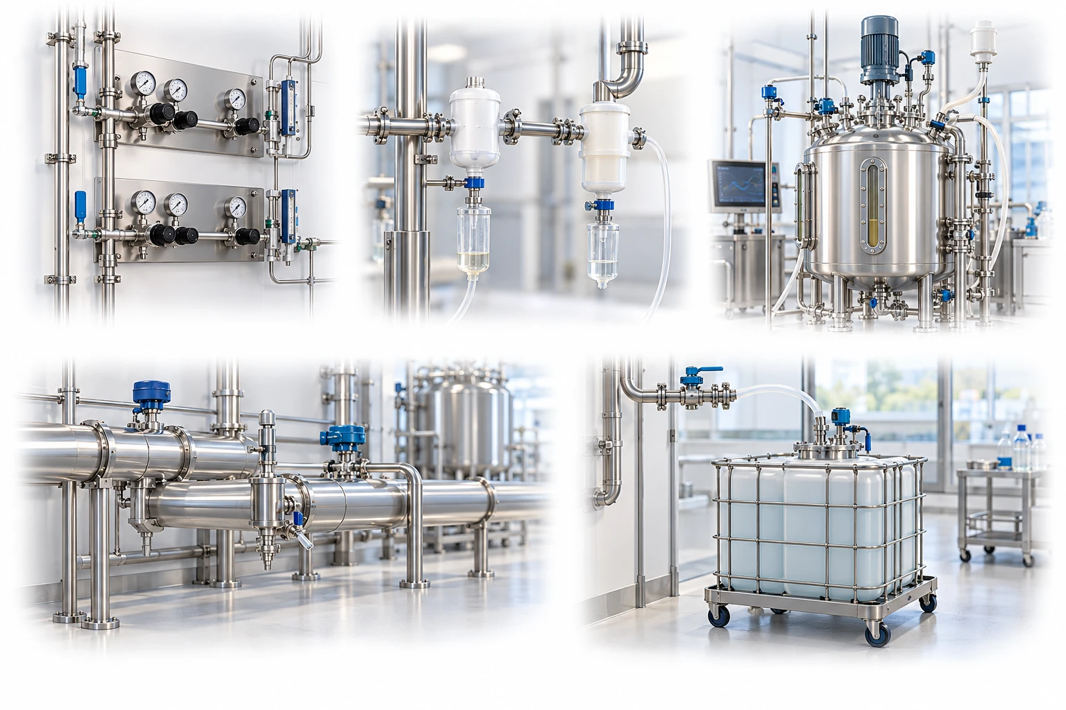
Gas supply and exhaust are independent. Define water, oil, particle and microbial quality for product-contact gas.
A conceptual illustration created to explain equipment and application locations. It is not an actual product photograph, installation photograph or piping/wiring design.
Scroll horizontally to see the complete flow.
Gas leaves during filling and enters during draining. Distinguish the vent filter from the liquid point-of-use filter. Check condensation, wetting, SIP conditions, and the tank pressure limits.
These conceptual views explain flow direction. Actual piping, wiring and physical flow rates require a separate design.
Define the intended use and conditions to identify the required role of each item.
Distinguish process-contact gases, tank vents, and water points of use.
Check the flow and pressure required during filling, draining, heating, cooling, and SIP.
Establish plans for integrity testing, condensate management, and periodic inspections.
Performance data for liquid filters cannot be directly applied to gas filtration. Review hydrophobic membrane condition, condensate, SIP, maximum gas flow, and tank pressure limits together, and clearly define the role of filters in water systems.
Scroll horizontally to review all columns.
| Process objective | Step to review | Selection evidence |
|---|---|---|
| Tank vents | Hydrophobic filters | Maximum filling and draining rates, thermal breathing, and allowable vacuum and pressure |
| Process gases | Pretreatment + final gas filters | Particles, oil, moisture, and microbial retention validation under gas conditions |
| SIP and condensation | Drainage and thermal management | Durability under repeated sterilization, differential pressure, and potential wetting |
| PW/WFI | Purpose-specific point-of-use assessment | Water quality, temperature, sanitization method, and hygienic design |
These examples start the application review. Pore size or nominal rating alone does not establish suitability or retention; confirm with the actual process fluid and supplier evidence.
Check the flow the vent must accommodate during rapid cooling or draining.
Distinguish standard flow from actual flow and absolute pressure from gauge pressure when sizing.
Investigate the causes of endotoxin and microbial problems in water across generation, storage, distribution, and sanitization.
Gas permeability may decrease, increasing differential pressure. Review condensation, liquid contact, and drying and sterilization procedures together.
No. Water quality requirements and the control and validation of the generation, storage, and distribution systems must all be met.
These details help narrow the configuration and the evidence to review.
Selection, replacement or quantity and lead-time review. Start with the information you have.
May we use Google Analytics, Google Ads and ChatGPT Ads to measure visits and completed enquiries? Learn more