
Define the humidity-control purpose
Define the target range and permitted variation for each area, and seasonal and process loads.
Membrane humidifiers supply water vapor to HVAC/AHU and controlled-area airflows. Review target RH alongside actual air loads, water supply, drainage and control requirements.
Review selection pointsDiscuss this applicationReview product locations and fluid paths.
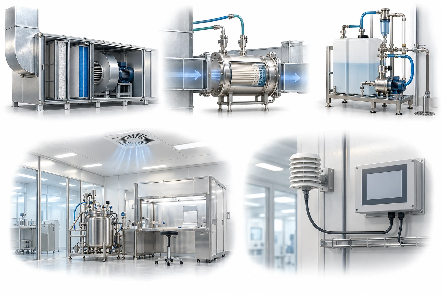
This is an illustrative HVAC integration for review. The module is not presented as a sterile barrier or a verified installed reference.
A conceptual illustration created to explain equipment and application locations. It is not an actual product photograph, installation photograph or piping/wiring design.
Scroll horizontally to see the complete flow.
Concept diagram of humidity control in HVAC. This configuration does not guarantee droplet control, sterilization, cleanliness, or GMP suitability. Check supply-water quality and drainage, RH load, sensor placement, and control in the actual HVAC design.
These conceptual views explain flow direction. Actual piping, wiring and physical flow rates require a separate design.
Define the intended use and conditions to identify the required role of each item.
Define the target range and permitted variation for each area, and seasonal and process loads.
Check water quality, supply and drainage, airflow, and temperature and humidity conditions before and after the device.
Define sensor placement and calibration, drainage, cleaning and scale management, and alarm and record methods.
A hollow-fibre membrane humidifier is a facility utility that transfers water vapour through the membrane from the water side into an air stream. It can be considered for humidity control in HVAC/AHU systems or controlled areas; it is not considered a device for direct contact with process solutions or products, or an air sterilization device. Verify target relative humidity, airflow, outdoor-air conditions and control response under the actual design load.
Scroll horizontally to review all columns.
| Process objective | Step to review | Selection evidence |
|---|---|---|
| Space and air loads | Area and air-conditioning conditions | Area, ventilation volume, outdoor-air conditions, air temperature and operating schedule |
| Humidity control | Target RH and response | Setpoint, permitted deviation, sensor placement and control stages |
| Water-side management | Water quality, supply and drainage | Manufacturer’s water-quality recommendations, hardness, conductivity, scale and stagnation risk |
| Hygiene and materials | Cleaning and water-contact components | Water-contact materials, drainability, and inspection, cleaning and replacement procedures |
| Monitoring | BMS and environmental records | Sensor calibration, alarms, history, data review and on-site verification |
These examples start the application review. Pore size or nominal rating alone does not establish suitability or retention; confirm with the actual process fluid and supplier evidence.
This equipment supports humidity control in controlled areas. The equipment alone does not guarantee suitability for product contact, sterilization or GMP compliance.
Water quality can affect membrane performance, scaling, maintenance and hygienic condition. Include stagnant water and inadequate drainage in inspections.
A space-wide average can miss localized deviations. Verify performance including ventilation volume, door opening and closing, process heat loads and sensor placement.
Required capacity varies with airflow, outdoor-air and temperature conditions, required response and operating hours. The load conditions must also be checked.
Humidification and control of airborne particles and microorganisms are different functions. Cleanliness and air-quality requirements must be reviewed separately through HVAC filters, facility design and monitoring procedures.
Provide the installation point and airflow diagram, minimum and maximum airflow, inlet temperature and humidity, and target RH. Include water quality, drainage and cleaning, sensor positions and BMS requirements. Assess suitability at the actual design load and maintenance conditions; air sterilization and direct product contact are outside this application scope.
Share the current configuration and operating conditions to review selection criteria and required evidence. Suitability and supply scope are confirmed for each application.
Confirm model suitability and supply scope through a technical review. Use each card to make an enquiry or review official manufacturer information.
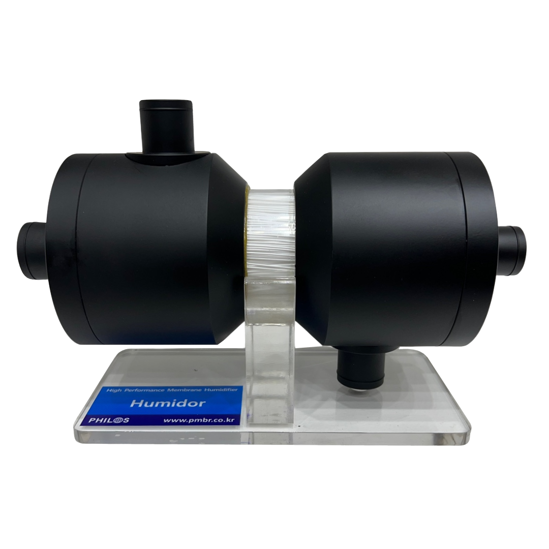
Manufacturer photograph of a display model showing the internal hollow fibers. Confirm the form and supply configuration of the operating module separately.
A hollow-fiber membrane humidifier transferring moisture from water or wet gas to air or gas.
Enquire about this productOfficial manufacturer product information ↗Product photographs and manufacturer images use permitted official materials and source links. Original explanatory schematics are identified separately from actual product photographs.
May we use Google Analytics, Google Ads and ChatGPT Ads to measure visits and completed enquiries? Learn more