Review tubing and distribution or sampling assemblies for media, buffer and product transfer. Mark the wetted path and aseptic boundary, and define component or preassembled supply.
Review product-contact transfer, small-bore supply and auxiliary utilities by duty.
Transferring process fluids
Single-use tubing
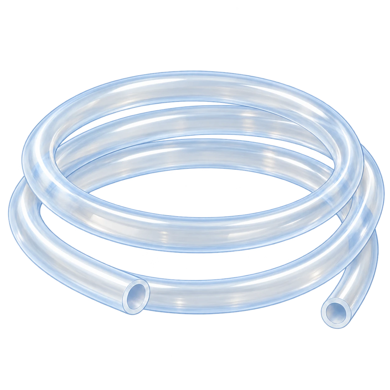
Review silicone or TPE tubing for media, buffer and product transfer, including pump segments. Assess pumping lifetime and material properties after sterilization.
Review: Material, ID and OD · pump segment · contact time and sterilization
Combining distribution and sampling branches
Tubing manifolds and assemblies
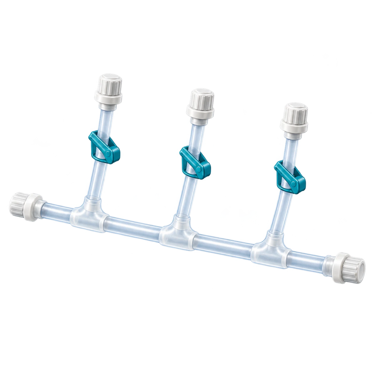
Review preconfigured assemblies linking supply, distribution and sampling points. Define branch count, valves and clamps on the process drawing.
Review: Branches and residual volume · connectors and closed boundary · leakage, sterilization and traceability evidence
Connecting equipment auxiliaries
Utility fittings
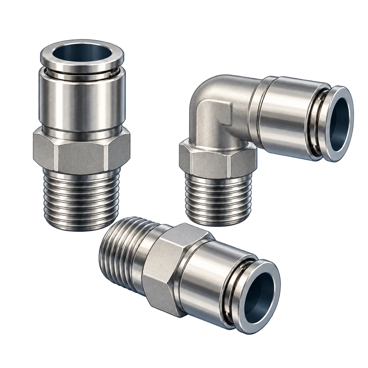
Connect auxiliary lines such as equipment pneumatics. Identify the configurations intended for product contact or aseptic connection separately.
Review: Gas and pressure · thread and tube dimensions · cleaning environment and contact duty
Illustrative product categories based on public product forms. Confirm the actual supply configuration and specifications against the intended conditions.
FIELD APPLICATION & FLOW
See the application in its industrial setting.
Review product locations and fluid paths.
APPLICATION IN CONTEXT
12345
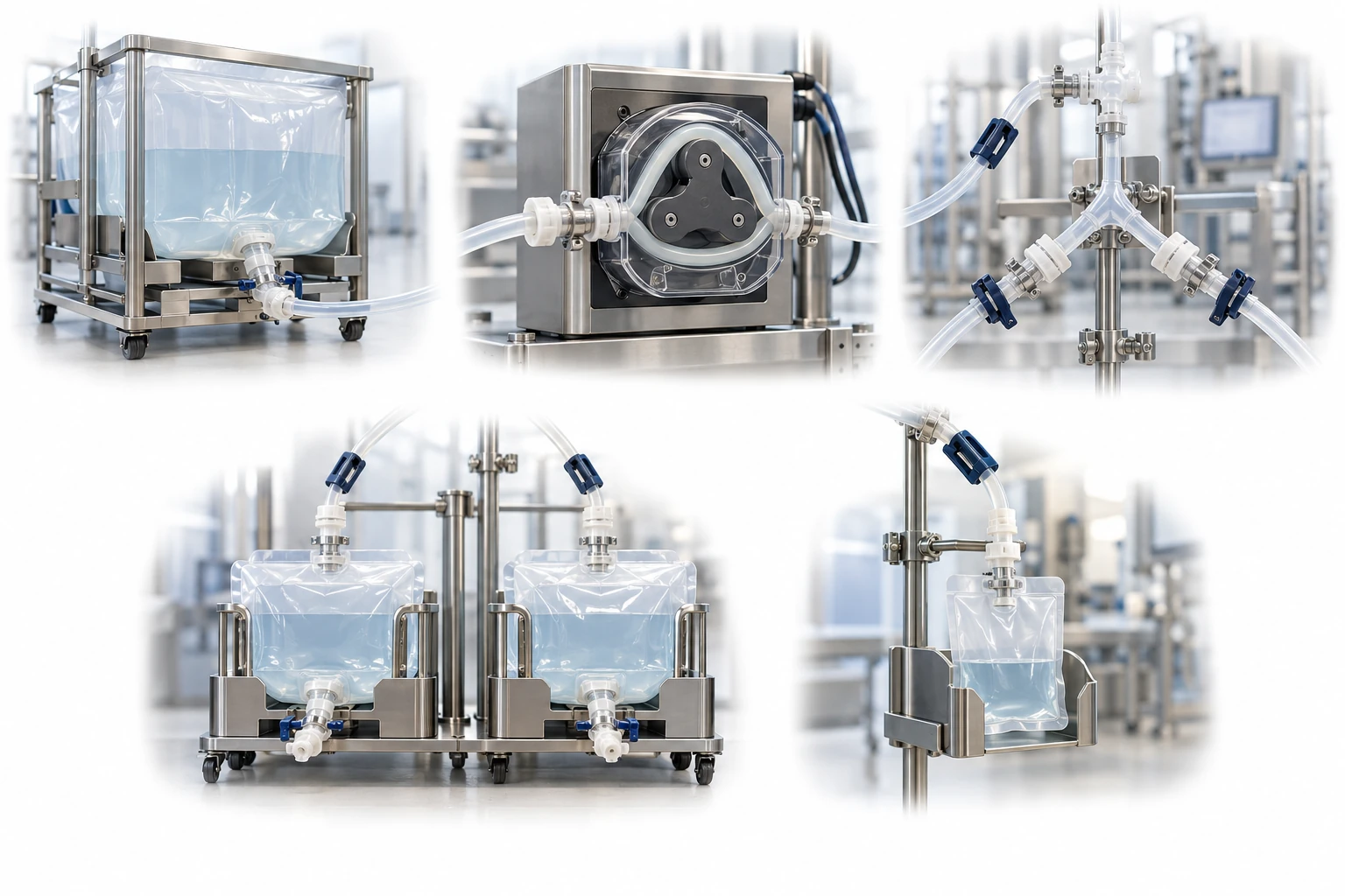
An illustrative single-use manifold connects supply, distribution and sampling branches, separating product-contact tubing from utility gas and signals.
01Supply vessel
02Pump segment
03Tubing manifold
04Process recipients
05Sampling bag
Connections to review
01 → 02 Supply vessel → Pump segment
02 → 03 Pump segment → Tubing manifold
03 → 04 Tubing manifold → Process recipients
03 → 05 Sample branch
Clamps or caps alone do not establish an aseptic connection. Review the connection method and complete product-contact path.
A conceptual illustration created to explain equipment and application locations. It is not an actual product photograph, installation photograph or piping/wiring design.
Connection principles and operating/test methods
2D PROCESS GUIDE
Process-liquid transfer · Pump section and connections
Fluid
PRODUCT TYPEBioprocess tubingIllustrative product form
Scroll horizontally to see the complete flow.
Concept of process-liquid transfer. Review the pump head, tubing material and dimensions, and actual duration of use as one combination.
Distribution and sampling · Define each branch path
Fluid
PRODUCT TYPESingle-use tubing manifoldIllustrative product form
Scroll horizontally to see the complete flow.
Concept diagram of branch paths. It does not mean that all shown branches are open simultaneously. Follow validated procedures for connection, distribution, and sampling.
Equipment utility line · Separate from product contact
Gas
PRODUCT TYPEStainless-steel utility fittingsIllustrative product form
Scroll horizontally to see the complete flow.
An auxiliary pneumatic-line example, selected separately from product-contact components. Confirm each connection is suitable for the actual fluid and cleaning environment.
These conceptual views explain flow direction. Actual piping, wiring and physical flow rates require a separate design.
01 — PROCESS
Where does each step fit?
Define the intended use and conditions to identify the required role of each item.
01
Process diagram and boundaries
Define supply, recovery, distribution and sampling points, and mark product-contact sections and sterile boundaries.
02
Tubing and branches
Review pump sections, tubing materials and dimensions, and the positions of branches, connectors and clamps as a combined configuration.
03
Assembly verification
Check the post-sterilization condition, leakage, packaging and transport, installation and use conditions.
02 — SELECTION
What should be selected and verified?
Fluid-contact tubing and connectors require different review criteria from auxiliary equipment components. Check materials, sterilization method, closure, change control and supply documentation for the entire fluid-contact path together.
Scroll horizontally to review all columns.
Application duty
Product to review
Selection evidence
Process-fluid transfer
Silicone or TPE tubing
Contact time and temperature, adsorption, extractables and leachables, and material properties after sterilization
Pump sections
Pump-compatible tubing
Head specifications, compression and recovery, operating duration, and effects on particles and quality
Distribution and sampling
Tubing manifolds
Number of branches and residual volume, connection method and sterile boundary, and sterilization and leak-test data
Auxiliary equipment lines
Utility fittings
Product contact status, gas and pressure, connection specifications and cleaning environment
Check wetted materials, connection combinations, sterilization or cleaning conditions and the actual operating envelope against item-specific evidence.
03 — OPERATING CHECKS
Confirm these points before selection.
01
Review the entire fluid-contact path
Treat bags, tubing, filters and connectors as one path, and document contact conditions and items subject to change.
02
Verify the basis for a closed connection
A cap or clamp alone does not establish an aseptic connection. Confirm the validation scope for the connection method and operating procedure.
03
Define the supplied unit clearly
The scope of documentation differs between supplied components and preassembled, sterilized assemblies. Define packaging, traceability and change-notification requirements.
04 — QUESTIONS
Frequently asked questions
Which is better, silicone or TPE?
Compare according to fluid-contact properties, sterilization, pump use, welding and sealing needs, and installation conditions. Do not rank them by material name alone.
Does assembly leak testing verify filter integrity?
Leak checks of bags, tubing and connections differ from filter-membrane integrity testing in their test objects and acceptance limits. Distinguish and validate the required tests.
Where should selection of an aseptic tubing assembly start?
Mark product-contact paths, connection timing and the required aseptic boundary on the process drawing. Then review tubing and connector combinations, welding or sealing needs, sterilization and validated operating procedures. Identify auxiliary parts such as pneumatic fittings separately by location and fluid-contact duty.
05 — APPLICATION REVIEW
Prepare the conditions for a technical discussion.
Share the current configuration and operating conditions to review selection criteria and required evidence. Suitability and supply scope are confirmed for each application.
✓Process drawing and connection timing; wetted path and aseptic boundary
✓Fluid, contact time, temperature, flow and pressure
✓Tubing material, ID, OD and length; branches, connectors and pump segments
✓Sterilization, welding and sealing needs; leakage and extractables or leachables evidence
✓Components or preassembled supply; documents, traceability, change notification and timing