
Flush and drain bags
Collect fluid used to wet or flush the filter through a closed path. For a downstream bag, confirm recovery volume and test-gas handling together.
Review PUPSIT bags, filters, vents and tubing as a connected assembly. Map the paths for wetting-fluid recovery, filter integrity testing and product filtration.
Review selection pointsDiscuss this applicationReview filters, tubing, valves, the recovery bag and tester within the complete arrangement.
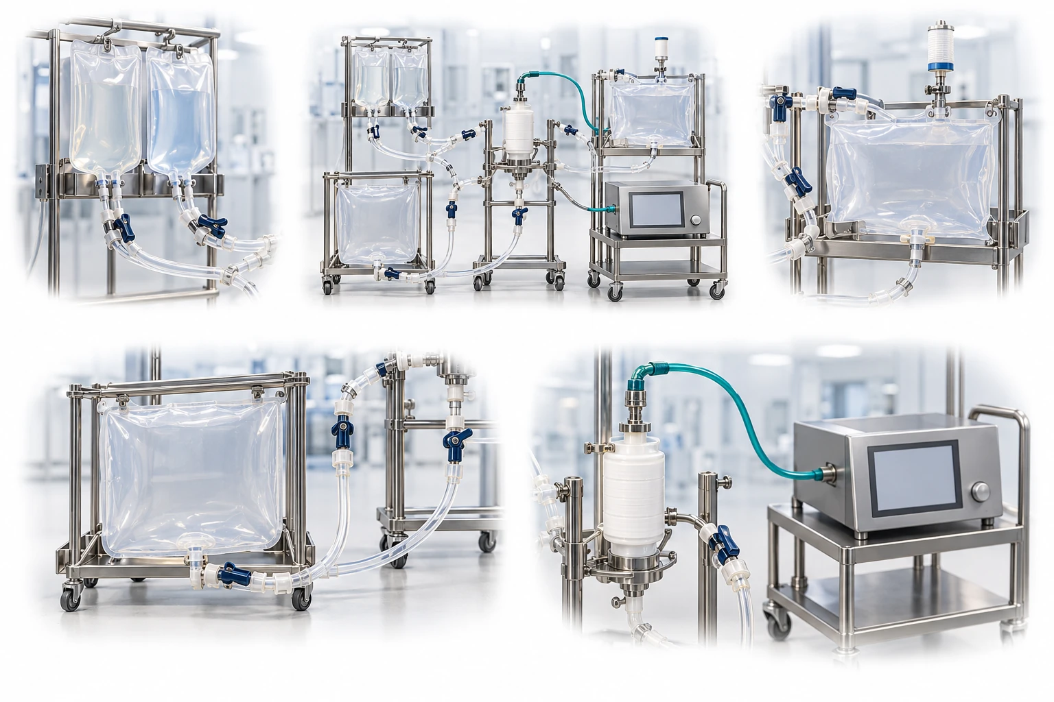
Numbers identify components. Actual wetting, test and product paths and valve sequences follow the approved drawing and validated procedure. Inclusion of the reusable frame, controls and tester and the supply scope are confirmed separately.
A conceptual illustration created to explain equipment and application locations. It is not an actual product photograph, installation photograph or piping/wiring design.
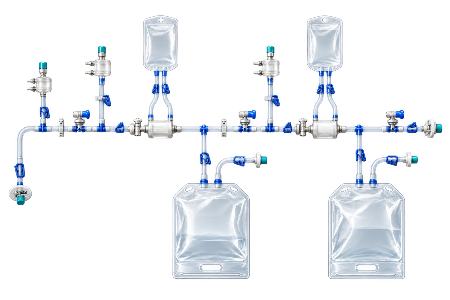
Scroll horizontally to see the complete flow.
An example of a collection bag connected to a vent. Liquid collects in the drain bag; gas exits through a separate vent. The product path is isolated at this stage. Review vent wetting and backpressure, actual bag fill volume, and support method.
Scroll horizontally to see the complete flow.
An example of handling test gas through a vented collection bag. The bag is not a pressure vessel: do not pressurize it with a blocked vent or when overfilled. For a sealed receiving configuration, check gas volume and allowable pressure separately. Follow validated paths for each test method.
Scroll horizontally to see the complete flow.
After confirming a passing test, send product to its dedicated receiving bag. Isolate the drain/vent-bag branch by the approved method and prevent test liquid entering the product. Valves are omitted from the diagram. Follow validated procedures for actual switching and post-use testing.
These conceptual views explain flow direction. Actual piping, wiring and physical flow rates require a separate design.
Identify supply, recovery, gas handling and product storage roles within the connected assembly.
Collect fluid used to wet or flush the filter through a closed path. For a downstream bag, confirm recovery volume and test-gas handling together.
Receive air and droplets from locations such as the filter vent, or discharge gas through a validated vent. Integration with the drain bag depends on the assembly drawing.
Supply water, buffer or another validated wetting fluid. Identify the supply and recovery roles separately, then confirm volume, connections and fluid quality.
Receive filtered product after testing. Keep it separate from recovery-fluid routing and review product-contact materials, storage and recovery.
Define the intended use and conditions to identify the required role of each item.
Compare the approved configuration drawing with the bill of materials. Check packaging and sterilization history, port, tubing and clamp locations, and support arrangements; distinguish the test path from the product path.
Fully wet the membrane with water or buffer suitable for the filter, or with validated product fluid. In configurations using water or buffer, collect the effluent in the designated drain bag and check fill volume and air venting.
While verifying the sterilized filter’s integrity before use, check that the downstream bag and vent handle the test gas appropriately. Validate that backpressure, vent wetting and bag expansion do not affect the test or connections.
After confirming a passing result, switch the test-fluid recovery branch and product receiving path in the approved sequence. Manage residual fluid and product losses, and follow the defined procedures for post-use testing, branch disconnection and disposal.
Review the bags, filters, exhaust components and tubing needed for final sterilizing filtration as one connected configuration. Use the complete drawing to confirm each bag’s role, test and product paths, and the scope of preconnection and sterile supply.
Scroll horizontally to review all columns.
| Bag or assembly function | Item to review | Selection evidence |
|---|---|---|
| Recover sufficient wetting fluid | Actual drain-bag working volume | Select based on the total wetting and flushing volume for each filter, approved number of repetitions, residual fluid and permitted fill volume. Do not decide using nominal capacity alone. |
| Handle gas appropriately | Closed gas-collection or vented configuration | For closed configurations, check the gas volume to be contained and expansion limits. For vented configurations, check gas flow, backpressure, wetting of the hydrophobic vent and installation orientation. |
| Fluid and material compatibility | Film, tubing, ports and seals | Review chemical compatibility, adsorption, extractables and leachables based on the composition of water, buffer or product fluid, temperature, contact time and post-sterilization condition. |
| Equipment interface and aseptic connection | Number and location of ports, and connection specifications | Identify the roles of the wetting-fluid inlet, drain and vent. Cross-check tubing inner diameter and length, welding and sealing suitability, aseptic connectors and space for clamp operation. |
| Manage pressure and mechanical loads | Bag, tubing, connections and support device | Distinguish the tester’s pressure setting from the pressure actually experienced by the bag. Compare conditions during vent blockage, valve misoperation and stalled drainage against the assembly’s permitted limits. |
| Minimize product loss and dilution | Residual volume, dead legs and path switching | Review residual volumes in the drain branch and tubing, fluid recoverability and consumption when wetting with product. Consider reuse of recovered fluid only when an approved procedure exists. |
| Maintain the configuration after sterilization | Sterilization method, packaging and shelf life | Check the supplied format and sterilization method, sterilization compatibility of the film and connections, packaging protection and storage conditions. Do not select on the assumption of unapproved resterilization or reuse. |
| Consistent supply and quality management | Validation, traceability and change documentation | Review drawings and the BOM, materials and scope of leak testing, lot and sterilization certificates, endotoxin and particle data, and change-notification conditions. Define the required items and acceptance limits for each process. |
Volume or film name alone is insufficient. Review the actual fluid, contact conditions, equipment compatibility and supplier evidence.
Label the roles and connection locations on bags and tubing, and confirm the valve switching sequence. Validate the paths to prevent test or drain fluid from entering the final product receiving section.
Incoming fluid or droplets that wet a hydrophobic vent can alter exhaust performance. Check liquid level, vent location, gas flow and downstream backpressure, and stay within the approved fill range.
Support the bag with the specified tray or hanger, and do not pull or kink the tubing. Check connection fixation and operator access positions with the assembly installed.
Confirm that wetting, draining, testing and switching to product are feasible at minimum and maximum throughput. For small batches, pay particular attention to the effects of residual wetting fluid and product on yield and concentration.
Leak testing of bags and tubing checks assembly tightness; filter integrity testing verifies the relationship to validated membrane performance. Distinguish test objects, detection limits, acceptance limits and records.
The PUPSIT BAG in this guide is an integrated assembly with preconnected bags, filters, vents, tubing and connections. Consider wetting-fluid recovery, gas handling during testing and the downstream sterile boundary together. Check the complete configuration drawing and bill of materials rather than selecting by bag capacity alone.
It depends on the configuration. Distinguish closed configurations that contain gas inside the bag from configurations that discharge gas through a hydrophobic vent. Review the capacity and pressure limits of closed configurations, and the exhaust performance and sterile barrier of vented configurations separately.
The amount of wetting fluid, flushing fluid and gas entering the relevant path is a more direct sizing basis than the product batch volume. Approved rewetting and repeat procedures, installation orientation and the manufacturer’s permitted fill range must also be considered, so a single fixed capacity is not recommended for all applications.
For product-fluid wetting, validate test acceptance limits and product compatibility, and evaluate consumption and recovery. The required inlet and recovery paths may differ from water or buffer wetting configurations; some configurations may not require a separate large-volume flush bag.
Distinguish the disposable fluid-path assembly from the integrity tester. Confirm which bags, filters, tubing, clamps and connectors are included using the drawing and bill of materials. An external tester, gas, wetting fluid and validated test procedure must also be prepared.
PUPSIT is pre-use post-sterilization filter integrity testing. This guide covers the single-use bags and connected configurations used in that process. Leak testing of bags and connections is a separate control item.
Provide the current process drawing and bill of materials, marking wetting-fluid supply and recovery, test-gas and product paths. Identify the disposable components and the separately used tester and gas supply so that connections, sterilization and documentation can be reviewed together. The final configuration and supply scope are confirmed for each application.
Share the current configuration and operating conditions to review selection criteria and required evidence. Suitability and supply scope are confirmed for each application.
Confirm model suitability and supply scope through a technical review. Use each card to make an enquiry or review official manufacturer information.
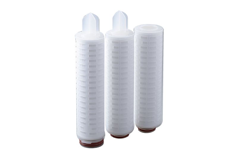
A hydrophilic PES 0.2 μm membrane cartridge described for sterilizing filtration of pharmaceutical liquids. Verify compatibility, microbial retention and integrity-test conditions for the actual process.
Enquire about this productManufacturer company information ↗Product photographs and manufacturer images use permitted official materials and source links. Original explanatory schematics are identified separately from actual product photographs.
This page explains selection considerations by application. It is not a commitment to supply every type, size or manufacturer’s product shown. Share the manufacturer and product code, or your configuration requirements, to discuss supply availability and outstanding checks.
Product-type and selection guide · Available configurations: confirm individually
Ask about supply for this configurationDocument availability and scope depend on the manufacturer, product code and configuration. Tell us which documents you need and the purpose of your review.
Availability and disclosure scope: confirm individually
This list does not guarantee that documents are held or available. Evaluation and approval for the actual process remain subject to the customer’s quality procedures.
Ask about required documentsSelection, replacement or quantity and lead-time review. Start with the information you have.
May we use Google Analytics, Google Ads and ChatGPT Ads to measure visits and completed enquiries? Learn more