
Understand the layout and ground
Check module height, spacing, and tilt, as well as ground material and seasonal changes.
Ground reflectance and the light that actually reaches the rear of a module are different quantities.
Review selection pointsDiscuss this applicationFollow light, sensor measurements and data connections.
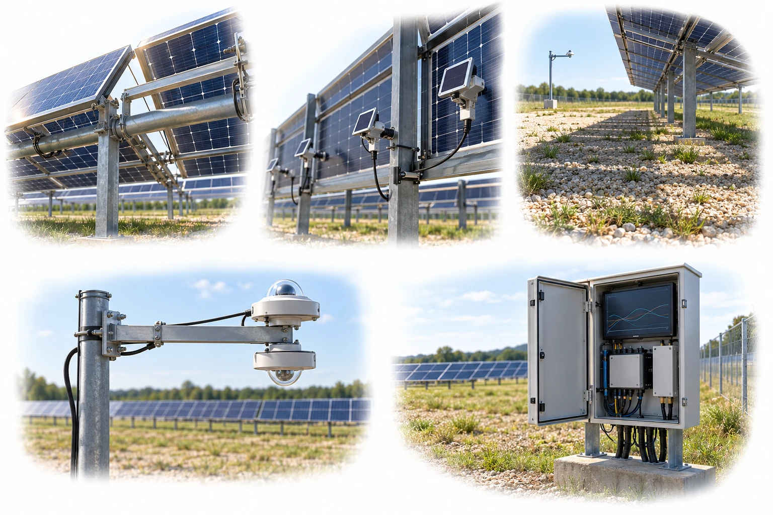
The up/down albedo pair is horizontal; rear POA sensors face the module rear. Representative measurement locations are reviewed for the actual array.
A conceptual illustration created to explain equipment and application locations. It is not an actual product photograph, installation photograph or piping/wiring design.
Scroll horizontally to see the complete flow.
Rear POA and ground albedo are different measurements. Select representative rear measurement positions with structural shading and variation between locations in mind.
Scroll horizontally to see the complete flow.
Up-facing and down-facing refer to the direction the sensors face. Albedo is the ratio of reflected to incident irradiance measured on the same reference plane.
These conceptual views explain flow direction. Actual piping, wiring and physical flow rates require a separate design.
Define the intended use and conditions to identify the required role of each item.
Check module height, spacing, and tilt, as well as ground material and seasonal changes.
Distinguish albedo measurements over representative ground from irradiance measurements at several rear locations.
Compare front and rear irradiance, temperature, and energy generation using the same time reference.
Albedo is the ratio of radiation reflected by the ground to radiation incident on it. Rear POA is the irradiance incident on the rear plane after the effects of structures, adjacent rows, height, and spacing; an albedo measurement alone cannot replace it.
Scroll horizontally to review all columns.
| Measurement objective | Item to review | Selection evidence |
|---|---|---|
| Ground reflectance | Upward and downward irradiance measurement | Representative ground, installation height, and shading from masts and sensors |
| Rear input | Rear POA | Obstruction by structures, spatial nonuniformity, and row-edge effects |
| Tracking arrays | Orientation and angle relationships | Rotation angle, backtracking, and sensor rotation with the tracker |
| Long-term comparison | Record changes in the ground | Snow cover, vegetation, moisture, ground treatment, and maintenance |
Review sensor suitability against the objective, installation environment, calibration evidence, system configuration and supplier specifications.
Record whether sensors are inside or outside a row, their height, and their position on the module so that the data can be interpreted.
Ground conditions and rear irradiance may be nonuniform, so select measurement points suited to the array layout and area.
Name the data channels clearly to avoid confusing the dimensionless albedo ratio with rear POA in W/m².
The relationship depends on the array structure, obstructions, and module bifaciality factor, among other factors. A simple proportional increase cannot be guaranteed.
Decide based on the array, target uncertainty, and spatial variation. Review representative locations first.
These details help narrow the configuration and the evidence to review.
Confirm model suitability and supply scope through a technical review. Use each card to make an enquiry or review official manufacturer information.
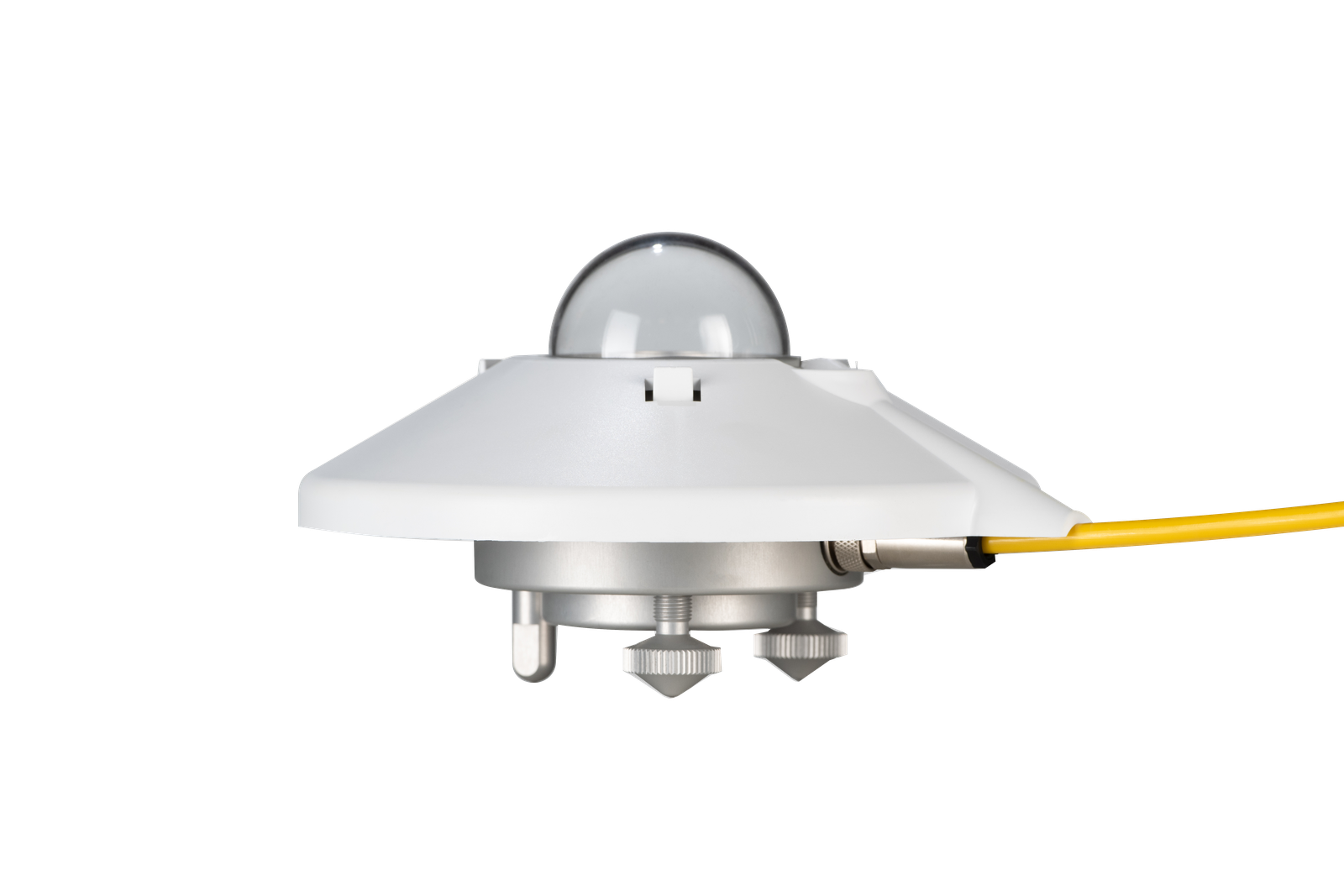
Class A pyranometer for digital solar irradiance measurement.
Enquire about this productOfficial manufacturer product information ↗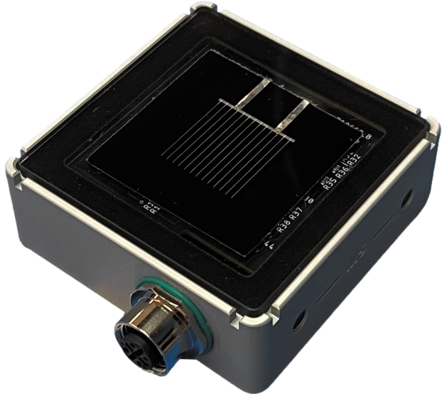
A PV reference cell for irradiance measurement in monofacial and bifacial systems.
Enquire about this productOfficial manufacturer product information ↗Product photographs and manufacturer images use permitted official materials and source links. Original explanatory schematics are identified separately from actual product photographs.
May we use Google Analytics, Google Ads and ChatGPT Ads to measure visits and completed enquiries? Learn more