
Select the module and mounting location
Check module technology, electrical ratings and plant structure. Select the target module and a nearby fixed vertical support.
Record periodic I–V curves and power from individual modules installed in the solar plant.
Review selection pointsDiscuss this applicationFollow light, sensor measurements and data connections.
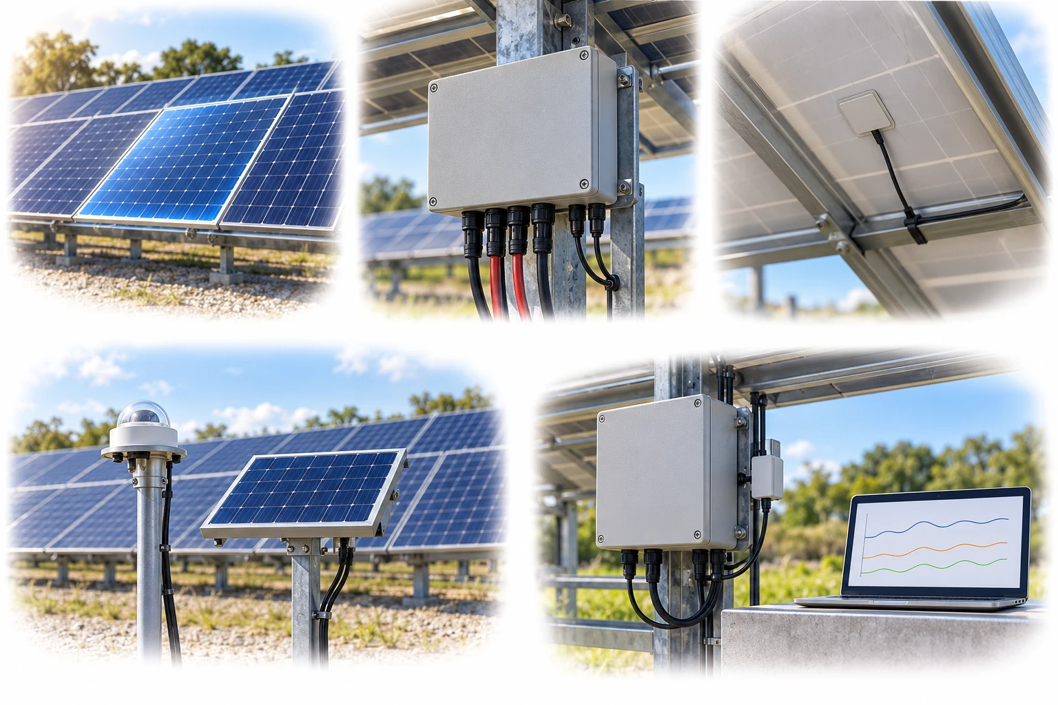
Mount the enclosure on a stationary support near the module with cable entries facing down. Separate module measurement connections, the string continuity path and measurement communications.
A conceptual illustration created to explain equipment and application locations. It is not an actual product photograph, installation photograph or piping/wiring design.
Scroll horizontally to see the complete flow.
Each unit periodically measures one selected module. Keep this scope separate from full-string scanning. Lines explain connection functions; use the installation guide for actual DC wiring, polarity and protection. Soiling assessment requires a clean reference and correction/normalization.
These conceptual views explain flow direction. Actual piping, wiring and physical flow rates require a separate design.
Define the intended use and conditions to identify the required role of each item.
Check module technology, electrical ratings and plant structure. Select the target module and a nearby fixed vertical support.
A unit with module measurement connections and a string continuity path performs periodic I–V sweeps. Record back-of-module temperature and relevant reference signals alongside the curve.
Compare curve and Pmax trends with irradiance, temperature and cleaning records. Use a clean reference and defined correction/normalization for soiling assessment, and transfer data to the logger or SCADA system.
A fixed measurement unit connects to one selected module in a power-producing array to record its current–voltage curve, maximum power and module temperature. Managed irradiance inputs and reference devices support comparison of soiling, performance changes and bifacial response. The measurement scope is the selected individual module; a full-string curve scan has a different scope.
Scroll horizontally to review all columns.
| Measurement objective | Item to review | Selection evidence |
|---|---|---|
| Individual-module measurement | I–V curve, Pmax, Isc, Voc, Imp and Vmp | Target-module voltage, current and power ratings, connectors and measurement range |
| Back-of-module temperature | Contact RTD | Rear-side attachment position, adhesion, cable restraint and temperature coefficients |
| Clean reference and normalization | Reference-module or reference-cell configuration | Cleanliness, calibration data, aligned measurement planes/timestamps and bifacial rear irradiance |
| Mounting and data integration | Fixed outdoor enclosure; RS485 / Modbus RTU | Nearby stationary support, downward cable entries, power, address, registers and data quality status |
Review sensor suitability against the objective, installation environment, calibration evidence, system configuration and supplier specifications.
One module does not automatically represent every module or plant-wide loss. Select measurement points with location, soiling, shading and module variation in mind.
Power changes alone cannot establish soiling, degradation or shading. Review the clean reference, irradiance/temperature correction and cleaning/maintenance records together.
Mount the unit on a stationary support with cable entries facing down. Qualified personnel must perform DC connection work according to manufacturer procedures and site safety rules.
Each unit of this type measures the curve of one selected module. An inline configuration connects between that module and its neighboring string connections. Design its scope separately from full-string testing.
Module-power measurement and soiling-ratio calculation have different requirements. Soiling assessment needs a clean reference module or suitable reference-cell configuration, with calibration and normalization.
Measurement data support cleaning, maintenance and further inspection decisions. Actual improvement depends on the loss mechanism, corrective action, cost, weather and operating conditions.
These details help narrow the configuration and the evidence to review.
Confirm model suitability and supply scope through a technical review. Use each card to make an enquiry or review official manufacturer information.
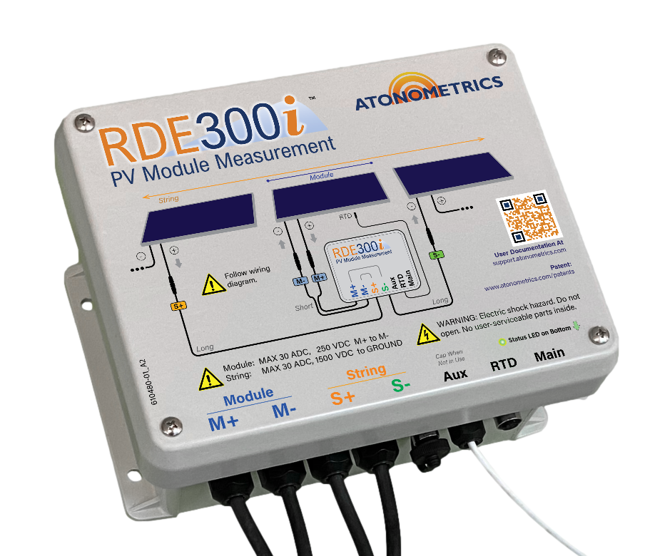
An in-situ PV module measurement system for I–V curves, performance and soiling assessment.
Enquire about this productOfficial manufacturer product information ↗Product photographs and manufacturer images use permitted official materials and source links. Original explanatory schematics are identified separately from actual product photographs.
May we use Google Analytics, Google Ads and ChatGPT Ads to measure visits and completed enquiries? Learn more