
Identify the device under evaluation
Confirm the module technology, performance assessment method, and required irradiance input.
Understand the differences between solar cell response and broadband irradiance measurement, and select a device that suits the purpose.
Review selection pointsDiscuss this applicationFollow light, sensor measurements and data connections.
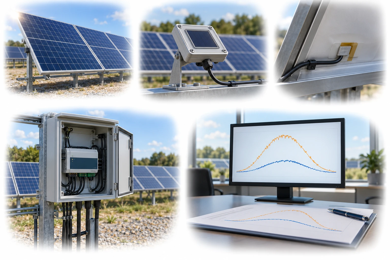
PV reference response differs from broadband radiometry. External back-of-module temperature and internal reference-cell temperature correction are distinct.
A conceptual illustration created to explain equipment and application locations. It is not an actual product photograph, installation photograph or piping/wiring design.
Scroll horizontally to see the complete flow.
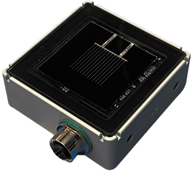
Measurement concept using the electrical response of a reference cell. Its response differs from a broadband pyranometer, so compare spectral, angle-of-incidence, and temperature characteristics.
These conceptual views explain flow direction. Actual piping, wiring and physical flow rates require a separate design.
Define the intended use and conditions to identify the required role of each item.
Confirm the module technology, performance assessment method, and required irradiance input.
Compare spectral mismatch, temperature correction, and calibration conditions.
Manage alignment with the module plane and cleaning, and analyze differences from the reference device.
Reference cells use the photoresponse of a solar cell. Their spectral, temperature, and incidence-angle responses differ from those of thermopile pyranometers, so select a device based on the module technology being evaluated and the measurement purpose, rather than price alone.
Scroll horizontally to review all columns.
| Measurement objective | Item to review | Selection evidence |
|---|---|---|
| Effective PV input | Reference cell or module | Spectral response and incidence-angle characteristics in relation to the device under evaluation |
| Broadband irradiance | Compare the purpose with that of a pyranometer | Measured physical quantity and correction method |
| Temperature effects | Cell temperature and compensation | Temperature coefficient, sensor location, and correction equation |
| Long-term consistency | Calibration and soiling management | Calibration traceability, glass condition, and drift |
Review sensor suitability against the objective, installation environment, calibration evidence, system configuration and supplier specifications.
Do not assume that a crystalline silicon reference cell represents all PV technologies equally well.
Check the difference between the raw signal and the corrected W/m² output, and confirm the calibration coefficient applied.
Review spectral, temperature, angle, soiling, installation, and calibration differences separately.
It depends on the physical quantity being measured and the application conditions. Assess the total uncertainty and how closely the device matches the module response.
Horizontal installation is appropriate for some measurement purposes, but measuring the input on the module plane requires alignment with that plane.
These details help narrow the configuration and the evidence to review.
Confirm model suitability and supply scope through a technical review. Use each card to make an enquiry or review official manufacturer information.
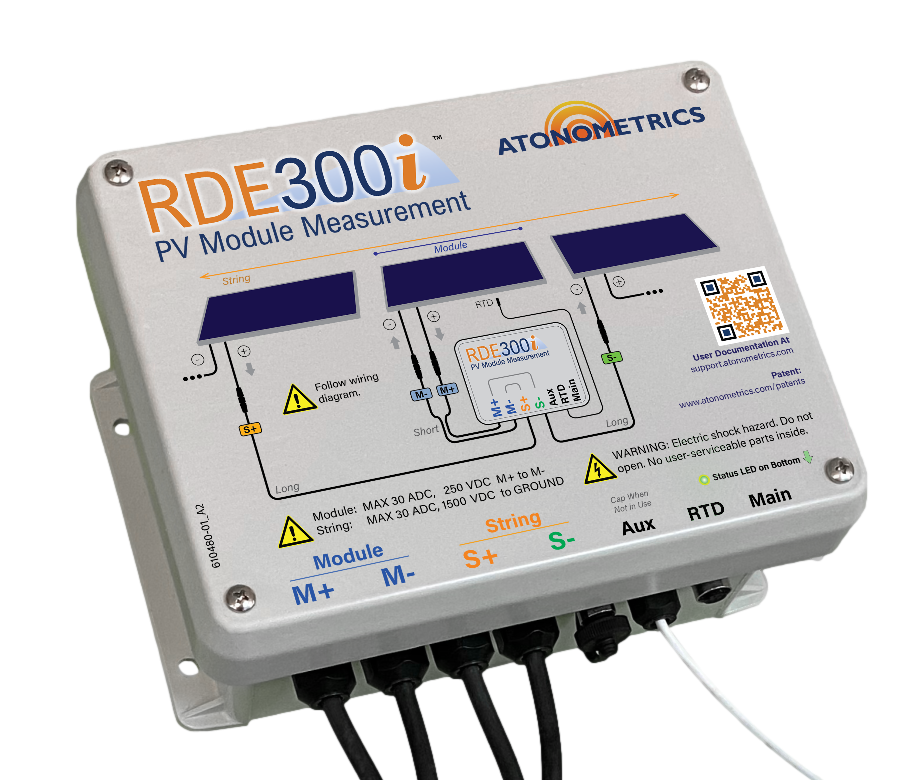
An in-situ PV module measurement system for I–V curves, performance and soiling assessment.
Enquire about this productOfficial manufacturer product information ↗A PV reference cell for irradiance measurement in monofacial and bifacial systems.
Enquire about this productOfficial manufacturer product information ↗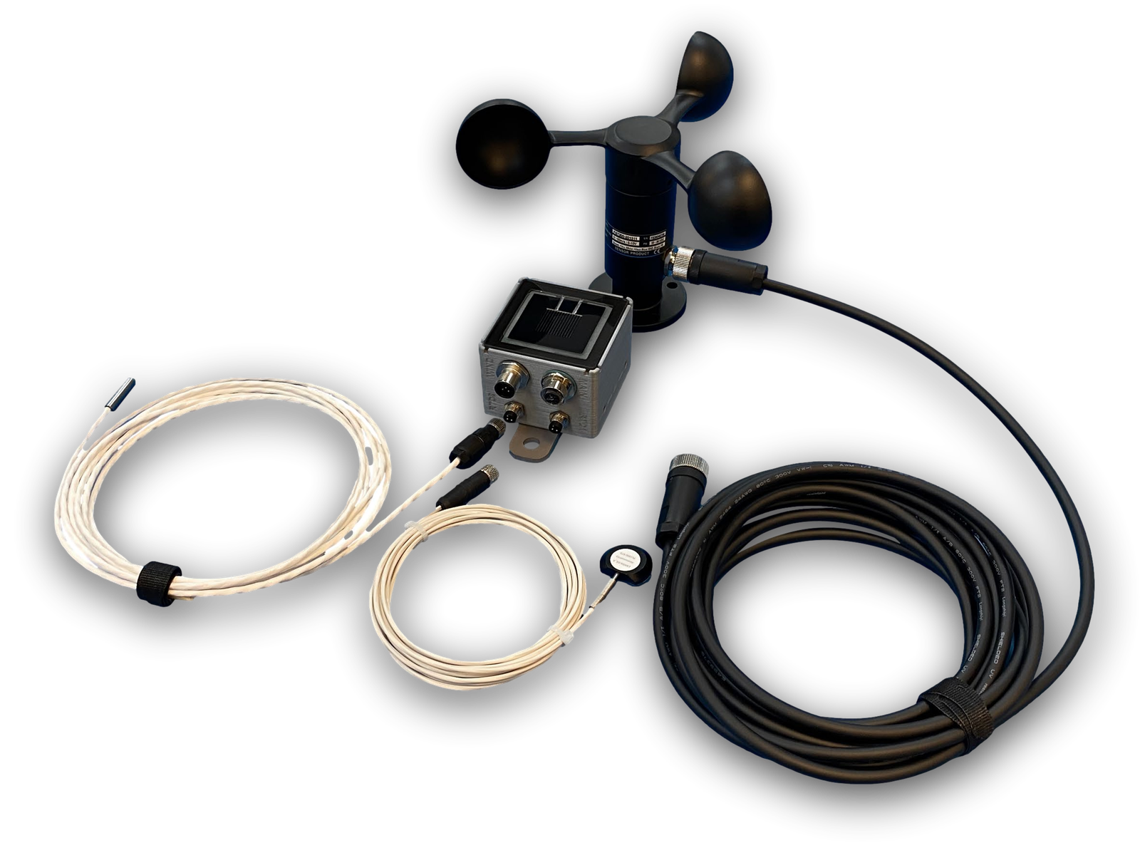
Example configuration connecting an RC22M reference cell with wind-speed, ambient-temperature RTD and module-temperature RTD sensors. Peripheral sensors and cables are optional; confirm the supplied configuration.
Enquire about this productOfficial manufacturer product information ↗Product photographs and manufacturer images use permitted official materials and source links. Original explanatory schematics are identified separately from actual product photographs.
May we use Google Analytics, Google Ads and ChatGPT Ads to measure visits and completed enquiries? Learn more