
Understand the soiling environment
Identify causes such as roads, farmland, industrial dust, coastal conditions, birds, and snow cover.
Review solar soiling sensors for contamination trends and cleaning decisions. Assess measurement principles, representative siting and rainfall or cleaning records alongside generation data.
Review selection pointsDiscuss this applicationFollow light, sensor measurements and data connections.
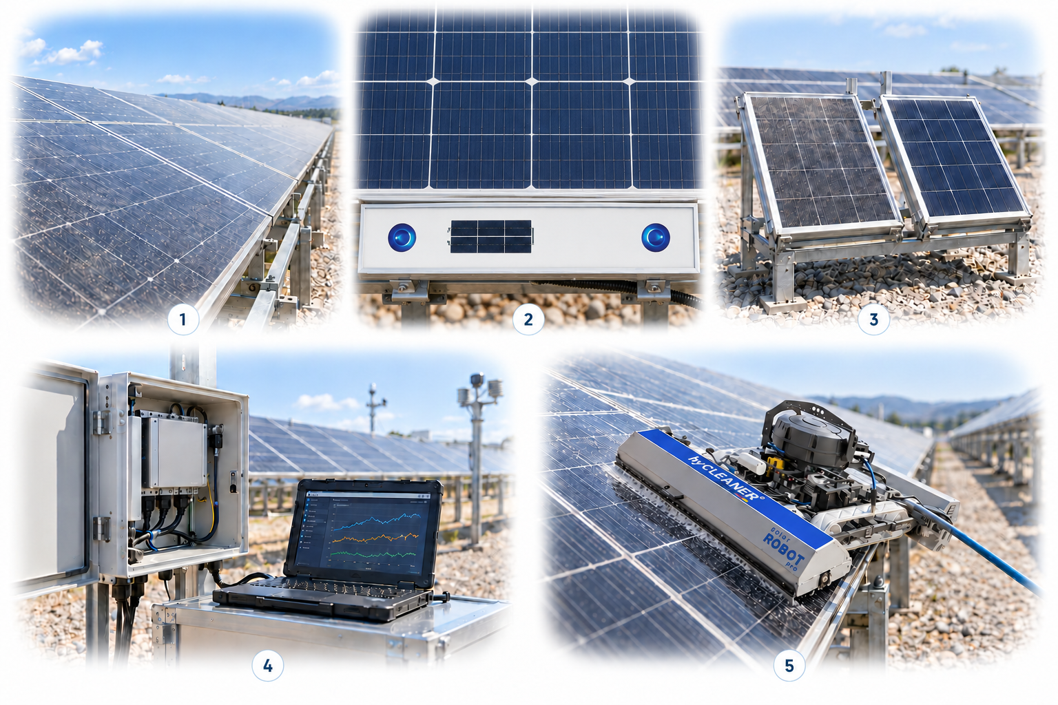
2 and 3 are distinct measurement methods, not devices connected in series. An optical value is not automatically the whole plant’s electrical loss. Confirm positioning and installation against manufacturer guidance. Dashboard traces are illustrative, not actual measurement data. For robotic cleaning, verify actual slope, module loading, water supply, safety and supplied configuration.
A conceptual illustration created to explain equipment and application locations. It is not an actual product photograph, installation photograph or piping/wiring design.
Scroll horizontally to see the complete flow.
Concept diagram of the general optical principle. Actual optical paths and conversion methods vary by product. This does not mean camera imaging or direct measurement of power output.
Scroll horizontally to see the complete flow.
Match the orientation, temperature, and characteristics of the two reference devices and maintain the clean reference. Decide whether to clean by considering measured loss, expected generation, cost, and rainfall together.
These conceptual views explain flow direction. Actual piping, wiring and physical flow rates require a separate design.
Define the intended use and conditions to identify the required role of each item.
Identify causes such as roads, farmland, industrial dust, coastal conditions, birds, and snow cover.
Compare the maintenance requirements and measurement ranges of reference-device comparison and optical methods.
Evaluate changes before and after cleaning in relation to irradiance, energy generation, rainfall, and work costs.
Comparing clean and soiled reference devices and measuring soiling optically use different principles. Record how representative the installation is, local dust characteristics, and rainfall and cleaning history together, and examine their relationship to generation losses.
Scroll horizontally to review all columns.
| Measurement objective | Item to review | Selection evidence |
|---|---|---|
| Direct comparison | Clean and soiled reference devices | Cleaning of the reference device; matching alignment, temperature, and device characteristics |
| Optical measurement | Optical principles such as scattering | Glass and dust characteristics, site-specific correction, and installation plane |
| Plant representativeness | Review multiple locations | Spatial variation in soiling, edge locations, and wind direction |
| Cleaning economics | Compare losses and costs | Expected recoverable energy generation, cleaning costs, operating conditions, and rainfall |
Review sensor suitability against the objective, installation environment, calibration evidence, system configuration and supplier specifications.
Estimated light transmission loss may differ from actual power loss caused by nonuniform soiling.
The cleaning condition of the comparison device and sensor correction establish the reference. Keep complete maintenance records.
Consider irradiance, temperature, and operating conditions together, rather than comparing only the energy generated on different days.
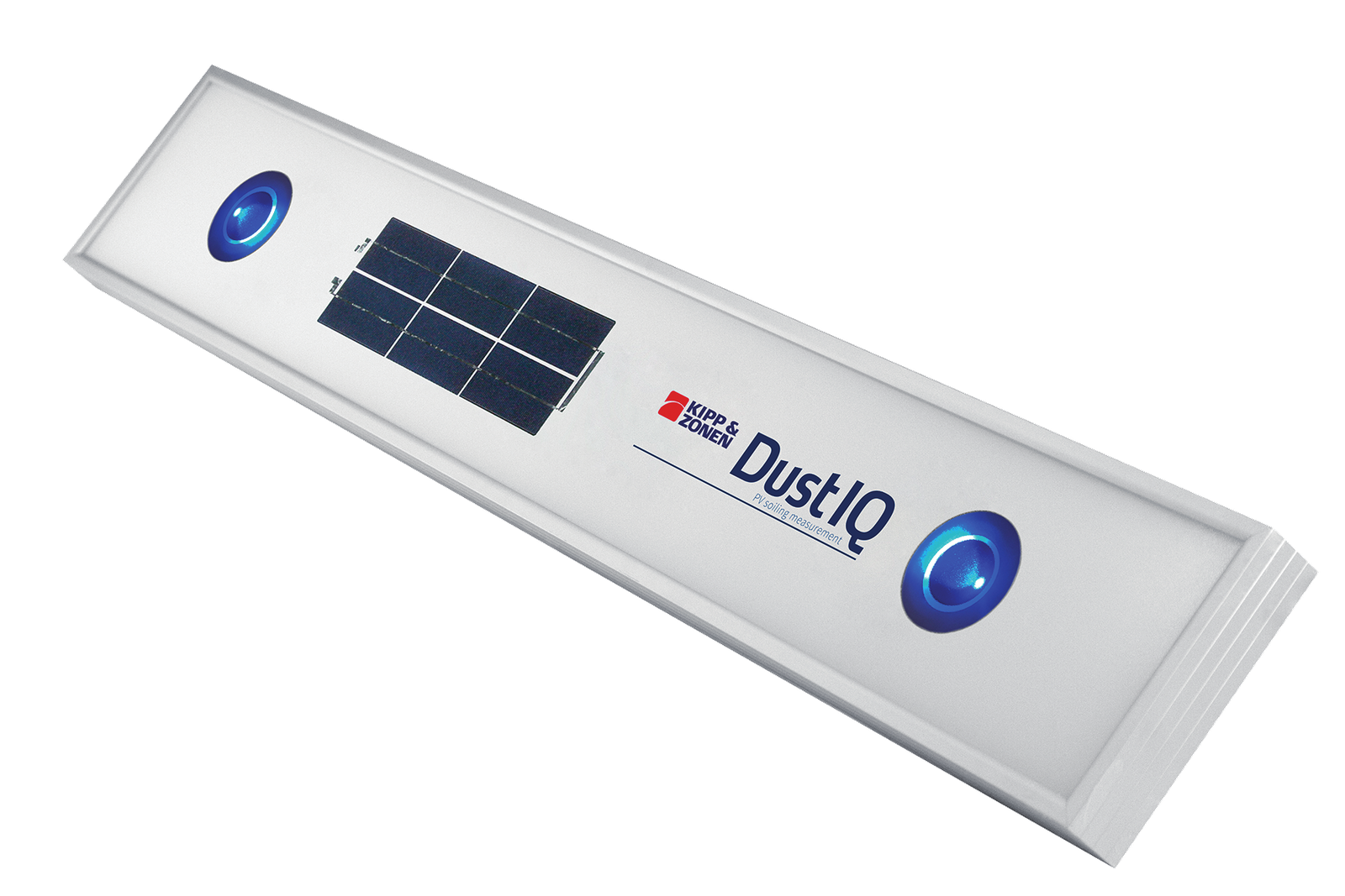
Types that use scattered light measure changes in light to estimate transmission losses caused by soiling. Distinguish them from image-analysis methods and confirm the measurement principle of each device.
Compare energy value, recoverable generation, cleaning costs, forecast rainfall, and site constraints together, rather than applying a universal threshold.
First assess whether its location represents soiling across the site. Compare array layout, tilt, wind and soiling sources, module glass and rainfall or cleaning history when selecting positions. Review the relationship between estimated soiling and actual generation loss, together with cleaning cost, energy value and expected rainfall.
Share the current configuration and operating conditions to review selection criteria and required evidence. Suitability and supply scope are confirmed for each application.
Confirm model suitability and supply scope through a technical review. Use each card to make an enquiry or review official manufacturer information.
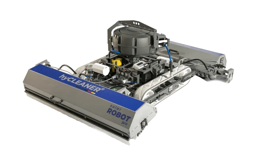
A semi-automatic, remote-controlled PV cleaning robot. Review site slope, surface, water supply and safety conditions.
Enquire about this productOfficial manufacturer product information ↗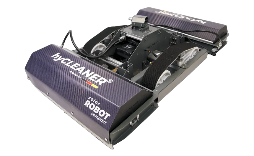
A semi-automatic, remote-controlled PV cleaning robot. Review site slope, surface, water supply and safety conditions.
Enquire about this productOfficial manufacturer product information ↗An optical sensor for monitoring front-side PV soiling transmission loss. Not intended for rear-side mounting.
Enquire about this productOfficial manufacturer product information ↗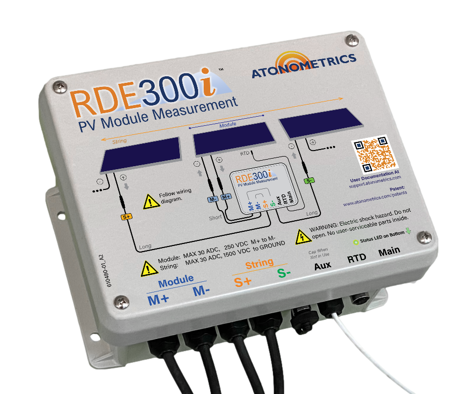
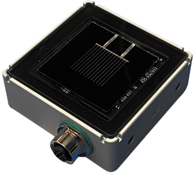
An in-situ PV module measurement system for I–V curves, performance and soiling assessment.
Enquire about this productOfficial manufacturer product information ↗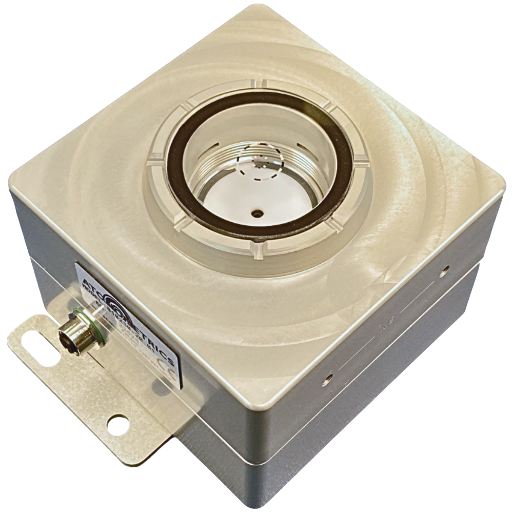
A camera-based PV soiling sensor.
Enquire about this productOfficial manufacturer product information ↗Product photographs and manufacturer images use permitted official materials and source links. Original explanatory schematics are identified separately from actual product photographs.
Explore how soiling losses and site conditions inform cleaning timing.
May we use Google Analytics, Google Ads and ChatGPT Ads to measure visits and completed enquiries? Learn more