
Container installation and bag deployment
Match the specifications of the support container and bag, and inspect the bottom port, folds and contact with protrusions.
3D single-use bags for bulk storage and supply of media, buffer and intermediates. Review support-vessel geometry, actual fill range and bottom drainage as one configuration.
Review selection pointsDiscuss this applicationReview product locations and fluid paths.
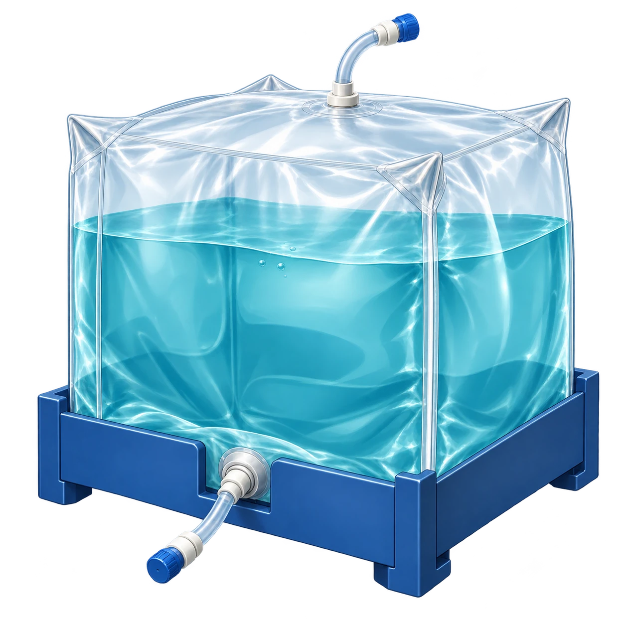
Match bag and support-vessel sizes. Vent arrangement, fill allowance and pressure follow the approved configuration.
A conceptual illustration created to explain equipment and application locations. It is not an actual product photograph, installation photograph or piping/wiring design.
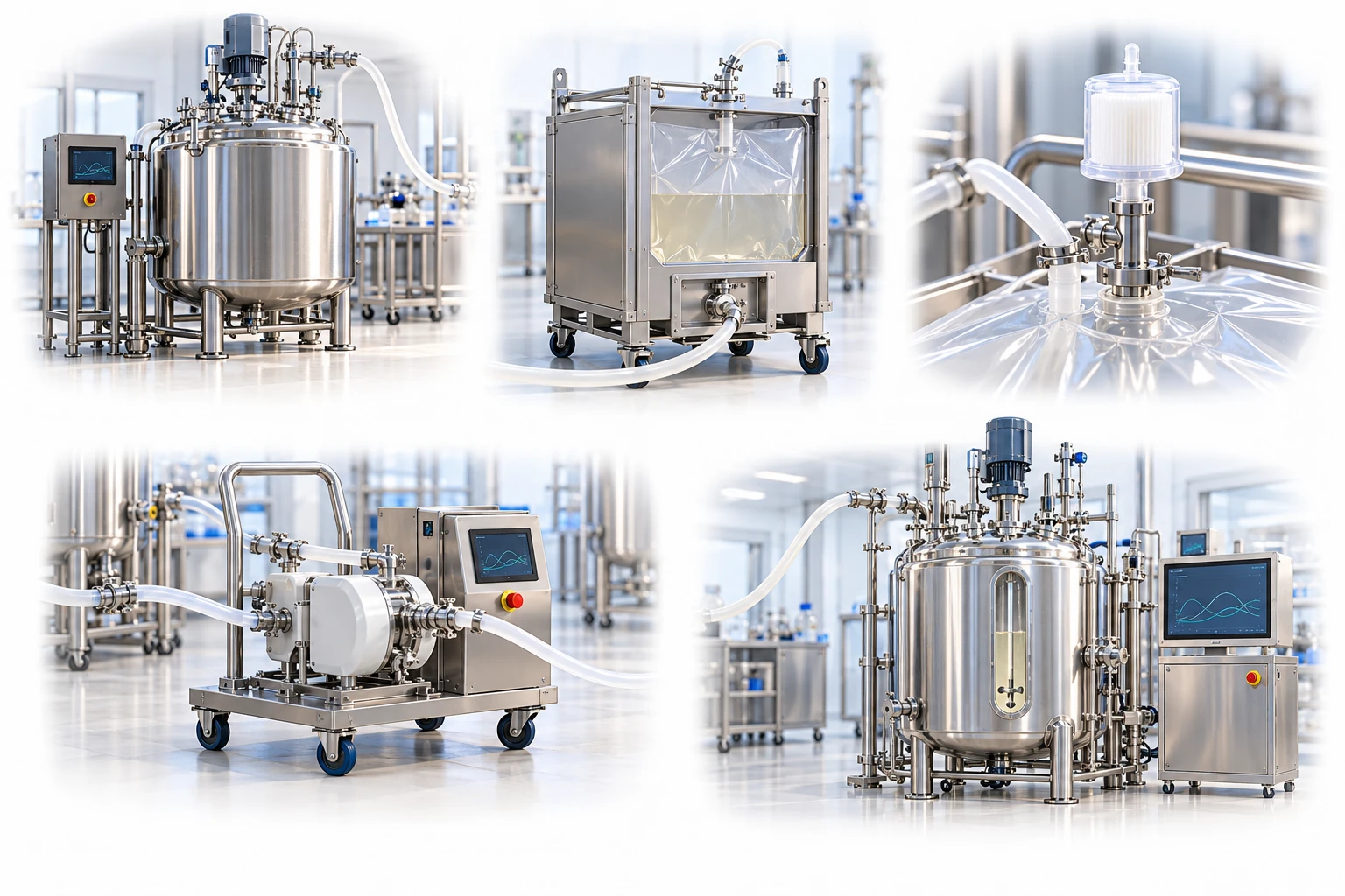
Scroll horizontally to see the complete flow.
An example using a bag installed inside a support vessel. Confirm transport suitability of the storage configuration separately. Do not pressurize it arbitrarily.
These conceptual views explain flow direction. Actual piping, wiring and physical flow rates require a separate design.
Define the intended use and conditions to identify the required role of each item.
Match the specifications of the support container and bag, and inspect the bottom port, folds and contact with protrusions.
Apply the approved fill volume and flow rate, venting and pressure conditions, and record storage time and temperature.
Supply the next process while checking pump flow, bag collapse and blockages in the drain or tubing.
A 3D bag must match the internal shape and installation arrangement of its support container. Check deployment during filling, fluid loads, the drainage path and transport conditions to ensure stable use in large-volume processes.
Scroll horizontally to review all columns.
| Bag or assembly function | Item to review | Selection evidence |
|---|---|---|
| Compatibility between container and bag | Shape and port alignment | Internal dimensions, supporting surfaces, drain location and installation method |
| Large-volume filling | Fluid load and deployment | Maximum working volume, filling flow rate, film folds and port stress |
| Maintain quality during storage | Film and storage conditions | Fluid-contact materials, effects of gas permeability on the product, time and temperature |
| Manage damage during transport | Transport system | Distinguish static storage, movement within the facility and off-site transport, and define the validation scope |
| Consistent downstream supply | Drain and pump interface | Permitted pressure and vacuum conditions, tubing inner diameter, residual volume and drainage time |
Volume or film name alone is insufficient. Review the actual fluid, contact conditions, equipment compatibility and supplier evidence.
Do not apply excessive pressure to the bag using pumps or gas. Follow the bag and assembly manufacturers’ conditions for permitted pressure, vent paths and response to blockages.
Folds in the bag and entrapment in container gaps can create localized loads. Standardize the manufacturer’s installation and deployment procedures and the operator’s checks.
A configuration suitable for static indoor storage is not necessarily suitable for transport. Evaluate movement, vibration and drop conditions with the bag filled, together with the external packaging.
Check the internal shape, sharp areas, bottom port, bag deployment and drainage method. Use a support container whose compatibility has been confirmed with the supplier.
Distinguish nominal capacity from the approved actual fill range. Determine the working volume using fluid density, installation state, transport requirements and the manufacturer’s specifications.
Compare bag geometry, deployment, approved fill range and drainage against the vessel’s internal drawing, dimensions and port locations. Include storage conditions and whether the filled assembly will be moved. Confirm bag and support compatibility and the permitted use through supplier evidence and actual installation conditions.
Share the current configuration and operating conditions to review selection criteria and required evidence. Suitability and supply scope are confirmed for each application.
This page explains selection considerations by application. It is not a commitment to supply every type, size or manufacturer’s product shown. Share the manufacturer and product code, or your configuration requirements, to discuss supply availability and outstanding checks.
Product-type and selection guide · Available configurations: confirm individually
Ask about supply for this configurationMay we use Google Analytics, Google Ads and ChatGPT Ads to measure visits and completed enquiries? Learn more