
Screen membranes and flow paths
Compare materials, MWCO, hollow fibers and cassettes, and flow channel dimensions.
Compare membrane MWCO, flow path, and operating conditions together to meet recovery and processing time targets.
Review selection pointsDiscuss this applicationReview product locations and fluid paths.
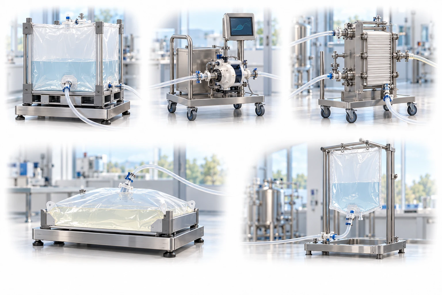
This UF/DF example retains the target product in the retentate. Other separation objectives may use a different product outlet.
A conceptual illustration created to explain equipment and application locations. It is not an actual product photograph, installation photograph or piping/wiring design.
Scroll horizontally to see the complete flow.
Retentate recirculates to the feed vessel, while permeate is discharged separately. During DF, add buffer according to the defined strategy and confirm the actual extent of buffer exchange by analysis.
These conceptual views explain flow direction. Actual piping, wiring and physical flow rates require a separate design.
Define the intended use and conditions to identify the required role of each item.
Compare materials, MWCO, hollow fibers and cassettes, and flow channel dimensions.
Track flux and quality as TMP, crossflow, temperature, and concentration change.
Review hold-up volume, flushing, final recovery, and flow conditions during scale-up.
In TFF, liquid flows along the membrane surface and a portion passes through it. Select the membrane and process conditions according to whether the target product must be retained and concentrated or low-molecular-weight components must pass through for buffer exchange.
Scroll horizontally to review all columns.
| Process objective | Step to review | Selection evidence |
|---|---|---|
| Retention and selectivity | MWCO and material | Target product passage into the permeate, impurity transmission, and actual separation curves |
| Operating range | TMP / crossflow | Flux saturation, pressure loss, shear, and temperature rise |
| Concentration and exchange targets | Concentration factor / DF volumes | Final concentration, conductivity, and analysis of residual components |
| Recovery | Module, piping, and recovery method | Hold-up volume, adsorption, dilution during flushing, and preservation of activity |
These examples start the application review. Pore size or nominal rating alone does not establish suitability or retention; confirm with the actual process fluid and supplier evidence.
Concentration polarization and fouling can cause flux to plateau. Use tests combining TMP and flow rate to establish a stable operating range.
Review flow paths, hold-up volume, shear, and cleaning, sterilization, and scale-up conditions for the target product.
Measure not only total recovered quantity but also product attributes such as aggregation, degradation, and biological activity.
Differences in materials, pore size distribution, flow paths, and test methods can lead to different actual retention and transmission performance.
A common approximation is (inlet pressure + outlet pressure)/2 − permeate-side pressure. Check the pressure measurement locations in the equipment and the manufacturer’s definition.
These details help narrow the configuration and the evidence to review.
Review feed, retentate and permeate pressures alongside TMP.
Consider operating conditions and possible membrane fouling when interpreting declining flow.
May we use Google Analytics, Google Ads and ChatGPT Ads to measure visits and completed enquiries? Learn more